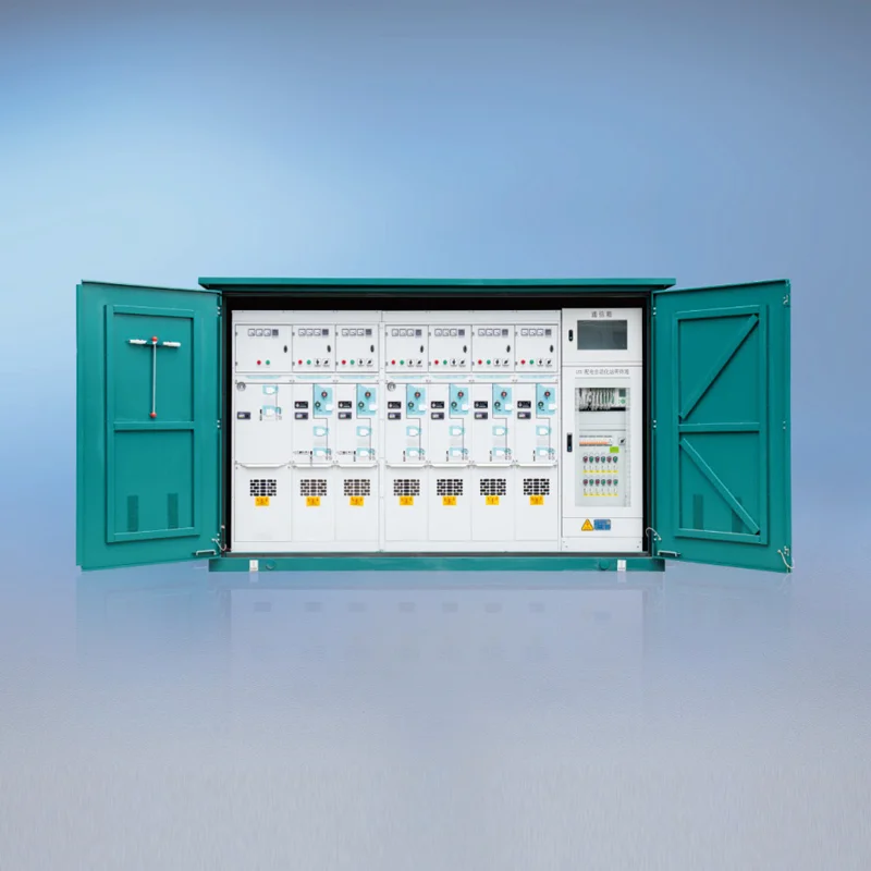
A Primary and Secondary Integrated Complete Ring Main Switchgear Station Terminal has an essential job of receiving, managing, protecting, distributing, and detecting electricity in a ring-based distribution system. It also consists of primary switchgear, protective apparatus, measuring instruments, controlling devices, communication means, and other auxiliaries in one complete package.
This equipment assists operators in connecting or disconnecting incoming and outgoing lines, isolating malfunctioning areas, protecting transformers and cables, and keeping the power flowing to other parts of the network. It also simplifies installation and increases visibility, reliability, and efficiency, by merging primary and secondary systems.
What Is a Primary and Secondary Integrated Ring Main Switchgear Station Terminal?
A ring main switchgear station terminal is a piece of equipment employed in medium voltage distribution in sub stations, utilities, industries, commercial buildings, renewable energy plants, and engineering works. Generally, it consists of a ring main unit (RMU) and various protection and control equipment.
The “primary” is the main power circuit where medium-voltage currents flow. It includes incoming feeders, outgoing feeders, busbars, circuit breakers, load-break switches, disconnectors, earth switches, and transformer connections.
The term “secondary” pertains to the voltage control, protection, measurement, monitoring, and automation systems that control the primary equipment. This includes protective relays, current and voltage transducers, advanced electronic devices, remote control units, and communication devices.
The system being designed and supplied as an integrated complete terminal means a single coordinated solution rather than a set of independent devices is achieved. This coordinated solution makes sure that the settings of protection mechanism, mechanical interlocks, control logic, wiring, communication interfaces, and commissioning process function correctly.
The Main Function Explained
The main aim of the terminal for primary and secondary complete integrated Ring Main Switchgear stations is to control medium voltage electricity with precision and safely, giving operators correct information of its operational status.
1. Receiving and distributing medium-voltage power
From one or more incoming feeders connected to the medium voltage line, the terminal extracts power that is then delivered to the relevant stations, plants, or consumers.
In a common ring setup, power can travel in either direction, giving it more versatility compared to conventional radial feeder systems. When one portion of the cable encounters a problem or requires repair, that section can usually be cut off from the remainder of the system while keeping the supply to all other connected loads from other portions of the ring, depending on the design of the network and the operating method.
2. Switching and isolating electrical circuits
The terminal of the station gives ability to control switch i.e. control the feeders and the transformer circuits. The load break switches are typically used to stop a current from flowing in a normal circumstance, on the other hand circuit breakers are more suitable for situations where advanced protections are essential and where more efficient switching process is needed.
Disconnects and earthing switches ensure visible or confirmed isolations during maintenance work. The proper mechanical and electrical locking is important in preventing unsafe activities, such as closing the earthing switch on the live circuit and opening the access compartment before the supply circuit has been isolated in a safe manner.
3. Protecting cables, transformers, and connected equipment
Protection devices sense unusual situations such as short circuits, overloads, earth faults, and faulty phases. Protection can be achieved through the use of fuses, overcurrent relays, and earth-fault relays, differential protection, or other application-oriented technology depending on the specific design used.
Upon discovering a fault, the protection system issues a trip command to the relevant circuit breakers or switches. Rapid clearance of the fault minimizes damage to cables, transformers, busbars, and other devices as well. Also, it makes it possible to keep the fault in question from spreading to other parts of the grid.
4. Maintaining supply continuity
The ring main system provides numerous advantages, and one of the biggest benefits is supply continuity. Any faults or planned maintenance can take place in one part of the network without needing to shut down the whole network. By opening the switches surrounding the faulty part of the network, supply can be restored to consumers via a different route if the situation allows it.
The capability of transferring power either automatically or manually is dependent on the layout of the equipment. Some configurations use a normally closed point, while others involve the use of automatic switching technology, motorized switches, and circuit breakers controlled from afar. The actual switchboard supplies continuity, although the complete protection and automation system are responsible for the last capabilities of the installation.
5. Providing measurement, monitoring, and remote control
The secondary system gathers information on the performance of the system. This information includes values of voltage, current, power, power factor, frequency, energy used, switch location, fault indication, and transformer temperature.
The details can either be displayed on the local control panel or sent to the SCADA system, energy management system, or utility control center. Remote surveillance is very helpful in the case of unmanned substations, renewable energy power plants, data centers, rail transport system, and widely spread distribution networks.
How the Primary and Secondary Systems Work Together
The primary devices make the physical switching and interruption of electrical power, whereas the secondary devices establish when and why an action must happen, examine the state of the network, and convey the results to the operators or more advanced control systems.
| System layer | Main equipment | Primary purpose |
|---|---|---|
| Primary system | Load-break switches, circuit breakers, disconnectors, earthing switches, busbars, fuses, cable compartments, and transformer feeders | Carry, switch, isolate, and interrupt medium-voltage power |
| Secondary system | Protection relays, meters, sensors, RTUs, PLCs, control panels, communication gateways, and auxiliary power supplies | Protect, measure, control, automate, and communicate operating conditions |
| Integrated station package | Coordinated wiring, interlocks, control logic, enclosure, testing system, and communication interfaces | Provide a complete, tested, and easier-to-operate distribution terminal |
The significance of integrating protection settings with control commands arises from the necessity to ensure their compatibility with the characteristics of the main circuitry. A well-engineered installation minimizes the chance of errors in the wiring, use of incompatible components, delays in commissioning, and other aspects of the communication between suppliers.
Typical Ring Main Unit Arrangement
A standard ring main unit might be made up of two ring feeder systems and one transformer feeder. The two ring systems link the terminal with both the incoming section as well as the outgoing part within the medium voltage grid. The transformer system is responsible for the supplying distribution transformer to lower the voltage down for the local applications.
Medium-voltage source A | Ring feeder 1 | [ RMU Station 1 ] ---- [ RMU Station 2 ] ---- [ RMU Station 3 ] | | | Transformer Transformer Transformer | | | Local loads Local loads Local loads | Ring feeder 2 | Medium-voltage source B or normally open point
The exact arrangement may consist of more distribution routes and bus-separation switches, room for measuring devices, voltage transformers, automatic actuating devices and certain protecting devices. Therefore, a diagram of the loop line stations should be accepted as a simplified version. The final drawing of a single wire must be based on the level of voltage, the level of faults, transformers, topography of the station, and utility requirements.
What Is the Working Principle of a Ring Main Unit?
A ring main unit is operated through planned clamping and selective isolation of the medium voltage ring distribution network.
Usually, in the ordinary state of affairs, the ring feeder switches stay closed, which allows the electricity to flow in the network. In addition, if the transformer feeds local consumers, the transformer feeder remains closed. The secondary protection and monitoring system is always verifying the values of current and voltage, the position of the switch, as well as signals relating to the faults.
The protection system detects any abnormal current or earth fault when a fault develops in the cable or connected circuit. Once a fault is detected in any section of the circuit, a circuit breaker or fuse-operated switch disconnects the faulted section. After that, operators or an automatic control system open other switches as required to create a safe isolated zone.
Once the damaged part is disconnected, the equipment in the normal parts of the loop can be energized from the opposite side. The restoration can be done either manually or automatically, depending on the type of device and control system in place. Before any maintenance activities, the isolated area is tested, discharged, and grounded as per the standard safety procedures.
The fundamental principle of selectivity means that in case of failure, only the minimum part of the network will be disconnected. This can be accomplished thanks to precise relay coordination, correct switch specifications, dependable interlocking and competent network analysis.
Key Components of an Integrated Station Terminal
Medium-voltage switchgear
The switchgear constitutes the primary electricity route. It may utilize air insulation, gas insulation, solid insulation, and/or a mixture of methods. The choice of technique is dependent on the voltage rating, operating environment, space constraints, ecological conditions, maintenance strategy, and project specifications.
Circuit breakers and load-break switches
Circuit breakers cut normal and fault currents due to the operation of the protective system. Normally, load-break switches serve to perform switching of the normal current and to isolate feeders. Some ring main units utilize load-break switches and fuses, while others employ circuit breakers and electronic relay systems.
Protection relays and sensors
The signals that are sent to the protection relay can come through a variety of devices such as current transformers, voltage transformers, Rogowski coils, capacitive voltage indicators, or other sensors. The electrical state of the system is evaluated by the relays, and upon satisfaction of the preset protection conditions, the relays issue a command to disconnect the equipment.
Control and communication equipment
The station can be operated both on-site and remotely via motor operators, local control switches, remote terminal units (RTUs), programmable logic controllers (PLCs), and communication gateways. The protocol that is typically in use is Modbus, IEC 60870-5-101, IEC 60870-5-104, or IEC 61850.
Interlocking and safety systems
The machine and electrical interlocks inhibit inappropriate operating processes. Additionally, safety measures during the operation and maintenance may incorporate the presence indicators for voltage, earthing switches, access controls, monitoring of pressure or density, and locks.
Why Use an Integrated Primary and Secondary Solution?
There are several advantages that the electrical contractors and project owners can use by combining the primary and secondary systems.
Faster project execution: Factory-assembled equipment reduces field wiring, site assembly, and interface coordination.
Improved compatibility: A coordinated system, which includes protection relays, switch operating mechanisms, sensors, control circuits and communication devices, is selected and tested.
Smaller footprint: In settings where there is minimal area available for electric substations, such as urban, modular or commercial buildings, a compact design can prove useful.
Better operational visibility: Through a single local or remote interface operators are able to obtain switching status, fault history, electrical measurements, and alarms.
Simplified maintenance: The use of standardized documentation, approved control logic and improved terminal design lead to faster troubleshooting and routine inspections.
Improved network reliability: When the system is designed and operated correctly, selective protection and alternative power paths reduce the length of outages.
Important Technical Specifications to Check
Finding the correct station terminal is not as simple as checking rated voltage. Appropriate equipment should take into account the complete electrical and environment conditions of a project.
| Specification | Why it matters |
|---|---|
| Rated voltage and insulation level | Confirms that the equipment is suitable for the system voltage and required dielectric withstand performance. |
| Rated normal current | Determines how much continuous load current the busbar and feeder can carry without exceeding temperature limits. |
| Short-time withstand and peak withstand current | Shows whether the switchgear can withstand the prospective fault current for the specified duration. |
| Short-circuit breaking capacity | Confirms that the circuit breaker or fuse can safely interrupt the available fault current. |
| Protection functions | Determines how effectively the system can detect overloads, phase faults, earth faults, and other abnormal conditions. |
| Ingress protection and enclosure type | Ensures that the equipment is suitable for indoor, outdoor, dusty, humid, corrosive, or restricted-access environments. |
| Automation and communication | Confirms compatibility with the site SCADA, energy management, or distribution automation system. |
| Standards and testing | Provides evidence that the equipment has been designed and tested in accordance with applicable international or local requirements. |
Medium-voltage switchgear is frequently defined by adherence to certain standards, including IEC 62271-200, IEC 62271-100, IEC 62271-102, and other relevant national standards. Different requirements apply to the switchgear, depending on factors like the kind of technology being used as well as its voltage level and installation procedures. Before approving the switchgear, it is recommended that customers ask for routine test reports, type test information if it applies, coordination protection data, wiring diagrams, and an entire diagram of the switchgear.
Installation, Commissioning, and Maintenance Considerations
Installation should be carried out by trained electrical technicians who are made aware about the safety measures of medium voltage. Furthermore, the site has to have appropriate footings, clearance of cables, earthing, ventilation or pressure relief systems, access space and auxiliary power.
The verification of insulation resistance, contact resistance, mechanical functioning, phase identification, interlocks, settings of protective relays, trip circuits, control circuits, remote signals, meter accuracy, and communication efficiency is usually done by the technicians during commissioning. Protection systems are tested using primary or secondary injection testing according to what is suitable to confirm correct functioning.
Switchgear technology and manufacturer instructions affect maintenance requirements. Routine activities may consist of visual inspections, cleaning, mechanism checks, checking cable terminations, performing protection function tests, reviewing event records, checking battery and auxiliary supplies, and verifying the reliability of earthing and interlocking systems.
All operations on medium-voltage gear must be performed according to an established isolation, lockout, voltage testing, discharge, and earthing process. Even if the device’s design is compact or integrated, it does not eliminate the need for training and strict electrical safety measures.
Frequently Asked Questions
What is the main purpose of a ring main unit?
A ring main unit is used for the control and protection of medium voltage feeders in a ring distribution network. It allows the operator to switch circuits, isolate defective sections, connect transformers, and supply power through another routing in case the network layout allows it.
Is a ring main unit the same as a substation?
Incorrect. A ring main unitcan be defined as a type of medium voltage switchgear apparatus. A substation may contain an RMU, transformer, Low Voltage Switchboard, protective device, metering equipment, battery system, and a structure. An RMU can be one vital component in a substation.
What is the difference between a primary and secondary system?
The primary system carries and switches the main electrical power. The secondary system monitors the primary circuit and provides protection, control, measurement, automation, and communication. In an integrated station terminal, these two layers are engineered to operate as one complete solution.
Can an integrated ring main terminal be controlled remotely?
Yes, if it is equipped with motorized switching devices, suitable protection and control equipment, a remote terminal unit or gateway, and a compatible communication connection. Remote-control capability must be specified during the design stage because it affects auxiliary power, control logic, cybersecurity, communications, and commissioning.
Does a ring main unit automatically restore power after a fault?
Not always. Some systems support automatic transfer or self-healing functions, while others require an operator to isolate the fault and close the appropriate switches manually. Automatic restoration depends on the network configuration, protection scheme, communication system, and approved operating philosophy.
What information should buyers provide when requesting a quotation?
Buyers should provide the system voltage, frequency, rated current, prospective short-circuit current, number of incoming and outgoing feeders, transformer rating, cable type and size, protection requirements, metering requirements, installation location, environmental conditions, communication protocol, automation requirements, applicable standards, and preferred enclosure or insulation technology.
How to Choose the Right Supplier
A reliable supplier should be able to provide more than a product brochure. Ask for a detailed technical proposal, single-line diagram, general arrangement drawing, protection and control description, rated performance data, routine test plan, applicable type-test evidence, communication list, installation instructions, and after-sales support details.
It is also useful to confirm whether the supplier has experience with projects similar to yours, including utility distribution, industrial plants, renewable energy, transport systems, data centers, or commercial substations. A supplier with strong application engineering capability can help verify fault levels, relay coordination, cable interfaces, earthing arrangements, and future expansion requirements before manufacturing begins.
The best solution is not necessarily the most compact or the least expensive option. It is the one that provides the required safety, reliability, protection selectivity, maintainability, communication capability, and lifecycle value for the actual network.
In summary, the Primary and Secondary Integrated Complete Ring Main Switchgear Station Terminal serves as the control and protection center of a medium-voltage ring distribution point. Its main function is to distribute power safely, isolate faults, protect electrical assets, support supply continuity, and integrate local or remote monitoring in one coordinated package. When the voltage rating, fault capacity, protection scheme, communication system, and installation conditions are correctly matched, it can provide a reliable and efficient foundation for modern distribution networks.